Hardware
Overview
The Hardware consists of a small PCB that contains an ESP8266 Microcontroller and some electrical components. The Microcontroller is the heart if the system. It runs the software to light up the LEDs and provides a WiFi interface to configure the device and interact with it.

The PCB has two connectors for LED strips. We decided to use WS2812B based Strips, as they are easy to use, cheap and broadly available. The LEDs have four connectors:
| Connector | |
|---|---|
| VCC | The supply voltage |
| Din | Data input |
| Din | Data output |
| GND | Ground |
The data consists of a serial signal that gets consumed by the first LED. The first LED consumes exactly 24 bits (or 3 bytes) of data. 8 bit (or one byte) for each of the three base colors (red, green, blue). Each LED pixel has internally a seperate LED for these colors. The data represents their brightness. With this you can “mix” almost every color for each LED.

All data that the LED recieves after these 24 bit is sent out to the D~out~ connection, which is connected to the Din of the next LED. With this you can pass all your data through one D~in~ of your first LED, which makes the wiring very easy:

Electronic Components
The big chunk on the Board that sits on the space labelled with U2 in the picture above is the microcontroller. The bit that overlaps the PCB is its WiFi antenna. The U1 labelled thing is a voltage regulator, that provides the microcontroller with stable 3.3V.
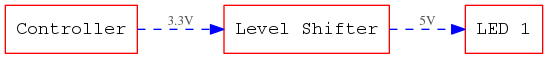
The LEDs uses 5V Voltage for operation and Data and the microcontroller we use needs 3.3V. To make sure, the LED recognize our data we need something called a Level Shifter. This piece “translates” the 3.3V signals to 5V. As we have two channels for LEDs we also have two of these level-shifters on the board. They consist of a MOSFET and two resistors. You can locate them by the Labels Q1 and Q2 on the board. Connected to these are to the connectors for the LEDs that are labelled with J1 and J2.
The little button on the PCB is connected to the reset pin of the microcontroller. Press this to reset (reboot) the controller.
The remaining components are the connectors and some resistors, diodes and capacitors. Some of them are necessary to bring the controller in the right state after boot, some are part of the level shifters. For more details we provide the Schematic of the whole board along with the source code of the Software. You can view the latest PDF Version online.
Connectors
The board has several connectors. They are all named with JX where X is the number of the connector. The connectors come in three types that serve different purposes.
| Name | Description |
|---|---|
| J1 | Output for LED strip 1. |
| J2 | Output for LED Strip 2. |
| J3 | Input port for two switches. |
| J4 | Pin header to program the ESP. It is compatible to the ESP-01 module. |
| J5 | The USB port to power the board. |
| J6 | Extension header containing all free pins. See schematic for allocation details. |
The connectors J1 and J2 can be used to connect LED strips to it. They carry the supply voltage and a signal from one of the level shifters. For your hat we use only J1. J2 is free to be used by your own creation - no matter if you attach more LEDs to your hat or something completely different.
J3 has two pins that are connected to two input connections of the microcontroller and a GROUND signal. you can add two switches between these and use them into your software to alter animations for example.
The pin header J4 is meant to be used to program your controller. It is wired exactly as the pin-header on a common ESP-01 module. You can find the pin allocation easily on the internet. ATTENTION: Take care that you use it in the right orientation: The row with the VCC pin is on the edge of the BlinkenHat board.
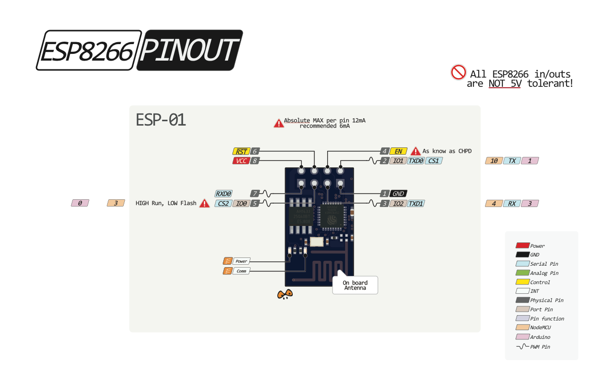
J5 is the USB plug to power the board. There are no other pins connected besides GROUND and VCC. So you wont be able to transfer any data to anywhere with that connector. We considered to make the board directly programmable via USB but this would have increased the complexity and the cost.
The last onnector J6 was built in for extensibility. It gives you access to all unused pins of the microcontroller and the 3.3V supply voltage of it. This can be useful if you want to extend or change the software to include sensors or add other things. The actual pin allocation is documented in the schematic of the board.